
Earlier this month, a member of the SWCM team headed to the Netherlands for a two-day visit, with members from the Channel Coastal Observatory, Fugro and RS Aqua to meet with the team at Datawell (see figure 1) – the experts behind our world-renowned wave buoys, Directional Waverider MkIII. The trip offered a rare, behind-the-scenes look at how these instruments are built and maintained and why they’ve earned their reputation for reliability.
Day One: Inside the Workshop
The first day began with a guided tour of the Datawell workshop. Almost every component of the buoy is built in-house, with astonishing precision. We watched technicians assemble the hippy sensor, a delicate piece of equipment wound with ultrafine wire – so fine, in fact, that a few spins of the buoy can snap it (see figure 2). All the electrical equipment, batteries and sensors are carefully installed into the buoy and then finally it is spray painted (see figure 3). Seeing this careful craftsmanship up close explained a lot about why our buoys have consistently outlived their expected service life (10 years).
Day Two: Presentations & Technical Insights
The second day focused on a series of presentations that revealed the science and engineering behind each element of the buoy system. Here are a couple of them summarised.
- Waverider: The Original Concept
The first talk revisited the early engineering that makes accurate wave measurements possible.
- The core idea is simple but demanding: a buoy must follow the orbital motion of the sea and measure its vertical acceleration. Double integrating that signal reveals the buoy’s “heave,” which tells us the height of passing waves.
- Engineers had to avoid “heave resonance,” design a small enough body to track even small waves, and manage both static and dynamic mooring forces.
- A passive vertical-reference unit—essentially a giant pendulum—provides a stable platform with zero power consumption (see figures 4 and 5), while elastic rubber moorings let the buoy move freely without stressing the anchor.
- Rubber Cord Applications
Natural-rubber mooring cords are key to buoy durability. Used for navigation, scientific, and larger wave buoys, these cords:
- Reduce peak loads in shallow water and during breaking waves.
- Limit horizontal spread so the buoy stays on station.
- Minimise wear on chains and other hardware.
Generally, our buoys are secured with a 15 m natural rubber cord (See figure 6), followed by a pellet float, then another 15 m cord, a length of chain, and finally a heavy anchor weight. This design might sound simple, but it’s incredibly affective.
Natural rubber is key. Unlike a rigid metal chain that would resist wave action and strain the buoy, the elastic natural cord absorbs wave energy, reducing the amount of strain exerted on the mooring. This flexibility protects the buoy and extends the lifespan of the entire system, resulting in one of the reasons why our network remains so robust, year after year.
- Solar Power at Sea
The final presentation showed how solar panels can extend the life of Waverider buoys (see figure 7).
- Horizontal panels feed boostcaps (super-capacitors) that store about 12 hours of energy with no chemical reactions or memory effect.
- A year-long test showed roughly 37 % of power came directly from the panel, 31 % from the boostcaps, and only 32 % from the primary battery—dramatically reducing battery use.
- Early issues with panel delamination were solved by switching to solvent bonding. Today, about half of all Waveriders use this hybrid solar system.
Beyond the technical insights, the visit was an excellent chance to connect with the Datawell team, share ideas, and strengthen the partnership that keeps our fleet of buoys resilient and adaptable for the future.

Figure 1: All attendees: Back row, left to right: Patrick Hales (Fugro), Niamh Brown (Fugro), Elizabeth Warwick-Champion (CCO), Isabel Kelly (SWCM), John Peters (RS Aqua), Martijn Bijwaard (Datawell), Tom Joosten (Datawell). Front row, left to right: Henny Joosten (Datawell), Thomas Dhoop (CCO), Eric Stoker (Datawell).
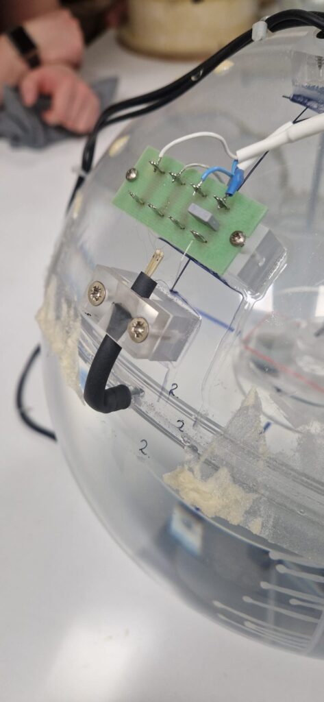
Figure 2: Ultra-fine wires used inside the hippy sensor.
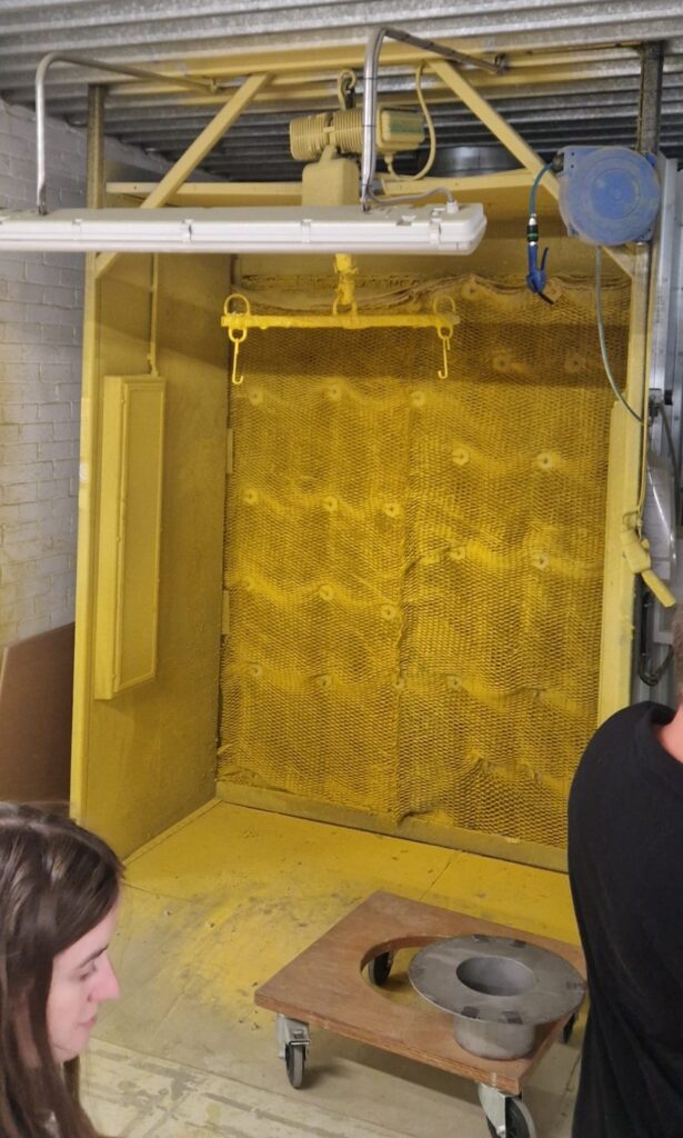
Figure 3: Wave buoy spray station.
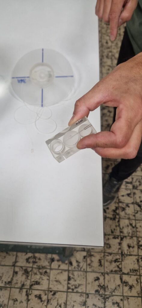
Figure 4: Components that make up the accelerometer inside the hippy sensor.
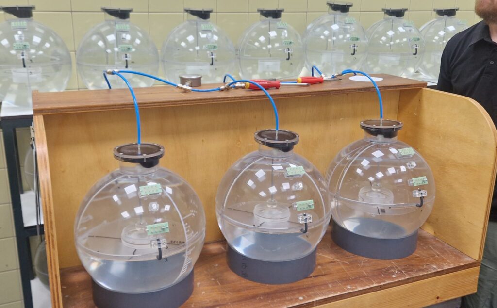
Figure 5: A collection of hippy sensors, which sit inside the wave buoy.
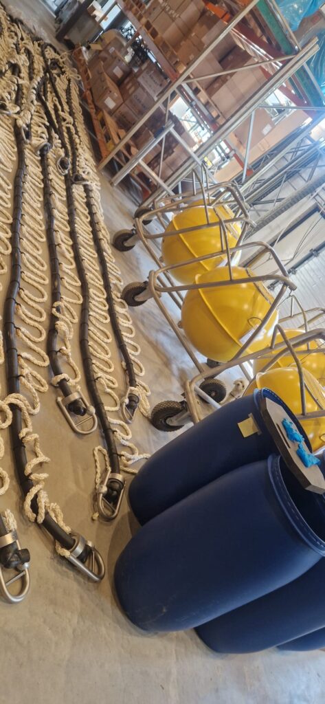
Figure 6: 50mm bungee mooring laid out with safety lines attached, ready to be deployed.
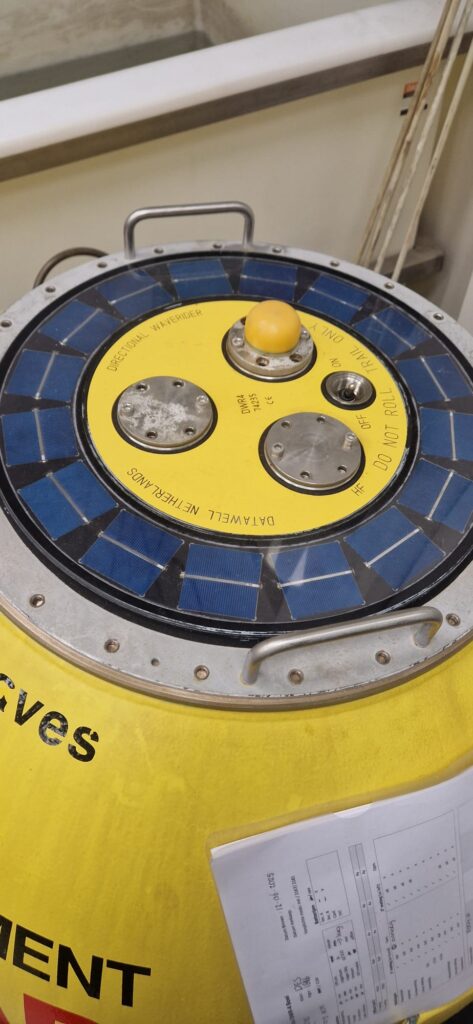
Figure 7: A Directional Wave Rider, with a solar panel hatch cover.
Let's Keep In Touch
We’ll keep you up-to-date with all the latest news on this website, but we’d also love to be able to send the occasional update.
We promise we'll only use your details to tell you about what we’ve been doing.